HW8 - Buzzzzz
Note
Notes on setting up the VM for AVR projects can be found in the Appendix; See AVR Assembly Setup
In this lab, we will explore the use of the timer to control a Piezo buzzer. We will use the polling scheme we went over. (Interrupts will happen in the next lab)
The buzzer looks like this:
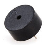
The particular device we will use was obtained from Jameco Electronics. (Search for part number 2098523 for details)
A Piezo buzzer is a simple device that vibrates each time a voltage changes across the pins of the buzzer. What this means is that if we turn on and off an output pin fast enough, we will hear a sound. How fast? Well, the particular buzzer we are using runs best at 4 kilohertz (4000 times a second or so). Make that your target speed.
We will use the timer to control this device. You will need to look over today’s lecture notes to set up the code to run this lab. The circuit for this lab is super simple. Just hook up the two power lines and connect one pin of the buzzer to ground, and the other pin to an output pin of your choice. The code will need to turn this output pin on and off fast enough to generate a sound.
Hooking up this device is simple. You plug it into the breadboard so the leads are on either side of the gutter that runs down the middle of the board. One side of the buzzer will be connected to an output pin on the Arduino, and the other pin will be connected to a ground pin on the Arduino.
Starting Point
Here is a sample “C” program that you can use as a starting point. This one will blink the LED on the Arduino at a reasonable rate. If you compare this code with the assembly code from the lecture, you wll see the same logic at work.
1 2 3 4 5 6 7 8 9 10 11 12 13 14 15 16 17 18 19 20 | // Example Arduino code to sound a Piezo buzzer
#include <avr/io.h>
#include <util/delay.h>
#define CLOCK_PRESCALE(n) (CLKPR = 0x80, CLKPR = (n))
#define BUZZER_CONFIG (DDRB |= (1<<4))
#define BUZZ_ON (PORTB |= (1<<4))
#define BUZZ_OFF (PORTB &= ~(1<<4))
int main(void){
CLOCK_PRESCALE(0);
BUZZER_CONFIG;
while(1) {
BUZZ_ON;
_delay_us(200);
BUZZ_OFF;
_delay_us(200);
}
}
|
Use the Makefile setup we are using for all AVR projects.
To compile this program, just run these commands:
make clean
make
make load
You should see your LED blinking.
Convert to Buzz
For your next step, convert this code so it toggles PORTD, pin 7. You will need
to speed up the loop so it makes some noise. That will take some experimenting
to get things set up right. You will know when this is working.
Connect your buzzer so one pin is connected to Pin 7 on the Arduino (PB7
on the chip), and the other is connected to ground (GND on the Arduino)
Convert to Assembly
For the last step, we will rewrite this as an assembly language program. I will make this easy. You can reverse engineer the code from the last step, and write a fully commented program that works the same way. Your should be able to figure out what the code is doing from your “C” source code.
Note
You can use the notes to see example code that does run.
Run this command to get an assembly language output file. You will need the new
Makefile system we went over in class for this to work:
make buzz.s(assuming your TARGET setting isbuzz)
This will be the file with assembly code in it.
Note
The code will not show register names, only the final numbers. You will
need to figure out which registers are being used by referring to your “C”
code, or the header files for the Arduino which can be could in
/usr/lib/avr/include/avr/. The iom328p.h file has definitions for
many of the registers in our chip.
