Step 8: First Machine
Read time: 35 minutes (8885 words)
We have all the code needed to build a simple test circuit and see if we can make it work.
We will set up a simple oscillator made up using three inverter components. An oscillator just generates a signal that changes back and forth, from zero to one. The circuit looks like this:
Think about what will happen here. Each inverter flips the input and sends the result on its way. If we assume the input to the first inverter is a one, then what will be the output from the third inverter be? What makes this work is the simple fact that it takes time for each inverter to do work. That means that the signal coming back around to the first inverter input will just change, and the cycle will continue. What we get out of this circuit, which has something called “feedback” going on, is a simple oscillator. That is just a fancy term for a clock! The output toggles back and forth between a zero and a one until you pull the plug!
Hey, we just constructed a simple clock part. We could use this in our simulator, but we might just simplify it a bit.
Why Three?
In some digital design classes, students actually build this circuit with real parts. Using just one inverter does not work so well, things are too fast to get a stable oscillator. The number of inverters has to be an odd number (why?), so the next choice is three. A convenient digital part has enough inverters in one package to set this simple circuit up and watch it oscillate. The resulting clock is not really stable enough for use in a real design, but it works well enough for our simulator!
Our challenge here is to build this simple circuit!
Wiring the Circuit
We need to assemble this circuit by hand for now. That means we create three Inverters (the constructor will take care of the attached pins), and set up three wires. The ugly code needed to assembly everything is tedious, but not hard. You just need to keep track of where things go.
We need a management class for assembling our system. We will call is the
Machine!
Here is the specification for our basic Machine:
1 2 3 4 5 6 7 8 9 10 11 12 13 14 15 16 17 18 19 20 | // Copyright 2018 Roie R. Black
#pragma once
#include <string>
class Machine {
public:
// constructor
explicit Machine(std::string n);
// accessors
std::string get_name(void);
// mutators
void run(void);
private:
std::string name;
int num_parts;
int num_wires;
};
|
This machine class has two basic functions. The first is to assemble our parts
into a circuit we can test. That will happen in the constructor for this class.
The second function is that run method, which starts up the machine.
Watching the Action
How are we supposed to see anything happen in this circuit? We have discussed the basic logic we will use to make things happen:
set up an infinite loop
Inside that loop set up an inner loop over all parts.
In the inner loop, call the
tickmethod for each part to generate new outputs.Set up another loop, this one over all wires.
Call the
tockmethod for each wire.
Since every component in a real digital circuit operates in parallel, we will consider the main loop our time loop. Rather than worry about how many nanoseconds it takes a part to do its work, we will just assume that each part takes one “tick” of our master clock to get done with processing. This give us a simple way to see how long it takes to get things done in our system.
Generating Diagnostic Output
We need some kind of output to make sense out of what is happening in our circuit.
In real digital circuits you cannot see inside of a typical digital part. That part has things going on inside of a sealed plastic shell. Instead, we can “probe” the pin attachment points by hooking up a piece of test gear that lets us watch the signals moving along on that pin.
Here is my favorite electronic tool, a Tektronix Oscilloscope.
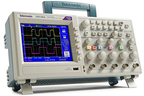
Note
Back in the 1970s, when I first started building my own circuits, I got to play with one of these gadgets at work. Back then, they cost around $10,000, so owning one was out of the question. A few years back, while wandering around at Fry’s, I saw a new one, now priced around $1000. It now sits on my electronics workbench at home!
Here is what I might see on my cool oscilloscope, if I set up this test circuit using real digital parts:

That real signal does not look as nice as we might expect. Real digital circuits cannot instantly switch from a zero to a one. It takes a bit of time to “settle” down to something the circuit can use as a zero or a one. We pay electronics wizards a lot of money to make real circuits work smoothly in the face of signals like this.
Simulating an Oscilloscope
Since we are not really concerned with real electronics parts in this class, we can ignore all of that messy wiggling signal stuff, and simply watch as our code switches the value on a wire from a zero to a one. We will build some code that will let us see our signals exactly like those shown above (only smoother) as we proceed with this project. For now, we will simply generate some interesting test output so we can prove the circuit does “oscillate”!
All we need to do is add code to our tock routine that displays what value
moved on that wire. We will also want to show the part and pin that generated
the signal, and indicate what part and pin received the signal.
This sets up a dilemma. How do we create a part that references a pin, and a pin that references a part. We cannot simply include the needed header files directly in these two classes.
This is called a “circular dependency”. Some folks try to avoid this, but there is a solution.
In the Component.h header file, we will include the Pin.h header file as we do normally.
In the Pin.h header file, we will not include the Component header file. Instead, we will use a “forward reference” for the Component class, and then set up a pointer so a pin can find the part it is “attached” to.
We will need to add an attribute to the Pin class that holds this new pointer, We will add methods in the pin class to fetch the part name of the “owning” part. We also set up methods in the wire class to fetch the part names from the attached pins.
This sounds messy, and you need to see the new code. Just for clarity, the modified files will be shown at the end of this note.
Machine Tests
Testing the entire “Machine” might not make sense as our simulator gets more complex. As a start, we will simply set up a test that the constructor set the machine name properly. Further testing will need to wait until we figure out what the machine really needs to do!
Here is the start on the Machine test code:
1 2 3 4 5 6 7 8 9 | // Copyright 2018 Roie R. Black
#include <catch.hpp>
#include "Machine.h"
TEST_CASE( "test machine constructor", "machine" ){
const std::string name = "TinySim";
Machine sim(name);
REQUIRE(sim.get_name() == name);
}
|
Machine Implementation
This is where we create the actual circuit. The constructor does the “wiring”
of our circuit. The run method makes the system do something. We have
three digital components, and three wires. So, we have a simple loop that runs
a few times, and inside of that loop we give all of the parts a chance to do
their magic during the tick phase, then we give the three wires their turn
to do something during the tock phase.
Notice that there is code after we complete the wire updates what displays some output on the console. This is a simple way to “watch” our circuit work. We will discuss this part of the code in more detail later.
1 2 3 4 5 6 7 8 9 10 11 12 13 14 15 16 17 18 19 20 21 22 23 24 25 26 27 28 29 30 31 32 33 34 35 36 37 38 39 40 41 42 43 44 45 46 47 48 49 50 51 52 53 54 | // Copyright 2018 Roie R. Black
#include <iostream>
#include "Machine.h"
#include "Inverter.h"
#include "Wire.h"
Inverter inv1("INV1"), inv2("INV2"), inv3("INV3");
Wire w1("W1"), w2("W2"), w3("W3");
// constructor
Machine::Machine(std::string n) {
name = n;
num_parts = 3;
num_wires = 3;
w1.attach_driven(inv1.get_out_pin("OUT"));
w1.attach_drives(inv2.get_in_pin("IN"));
w2.attach_driven(inv2.get_out_pin("OUT"));
w2.attach_drives(inv3.get_in_pin("IN"));
w3.attach_driven(inv3.get_out_pin("OUT"));
w3.attach_drives(inv1.get_in_pin("IN"));
}
// accessors
std::string Machine::get_name(void) {
return name;
}
// mutators
void Machine::run(void) {
inv1.get_in_pin("IN")->set_val(1);
for (int i=0; i < 5; i++) {
std::cout << "t" << i << ": ";
// let all the components do something
inv1.tick();
inv2.tick();
inv3.tick();
// let all the wires do something
w1.tock();
std::cout
<< w3.get_driven_part_name()
<< "."
<< w3.get_driven_name()
<< " -("
<< w3.get_val()
<< ")-> "
<< w3.get_drives_part_name(0)
<< "."
<< w3.get_drives_names()
<< std::endl;
w2.tock();
w3.tock();
}
}
|
Hey, we just built our first simple simulator. We have all the basic pieces in place to begin building a real system.
Example Output
Here is the output you should see from this simulated circuit:
CPU Factory Version: 3.0
sim starting...
t0: INV3.OUT -(0)-> INV1.IN
t1: INV3.OUT -(0)-> INV1.IN
t2: INV3.OUT -(1)-> INV1.IN
t3: INV3.OUT -(0)-> INV1.IN
t4: INV3.OUT -(1)-> INV1.IN
You might think about why that first time slice output seems off. Remember that our machine started life in some initialized state we created when we assembled the system parts. The system did not stabilize until all the parts started running. Once signals were properly moving through this system, the results are what we expect.
Assessing the Machine Design
Look at the code we wrote to hook up our circuit. Here are a few lines from that code:
w3.attach_driven(inv3.get_out_pin("OUT"));
w3.attach_drives(inv1.get_in_pin("IN"));
And here is the output we see:
t0: INV3.OUT -(0)-> INV1.IN
The two lines we need to write to connect the output from INV3 to the input
of INV1 can be derived from the output text we see here. Ignoring the
actual signal value that moved while the circuit ran, we can streamline this
line to just this:
INV3.OUT -> INV1.IN
This notation is called Register Transfer Language, something used in real
system design.
Here is an example data file we might write that tells us how to build this simple oscillator circuit:
PARTS
    inv1:   Inverter
    inv2:   Inverter
    inv3:   Inverter

CONNECTIONS
    w1: inv1.out -> inv2.in
    w1: inv2-out -> inv3.in
    w3: inv3.out -> inv1.in
This data file names the parts needed by setting up a part name and identifying the class name we will use for that part.
In the connection section, we identify each needed wire, then indicate what named pin on a previously defined part provides the signal, and what pin on a destination part receives that signal.
A little study will show you that every line we wrote in our Machine.cpp
file that set up our machine can be seen in this data file.
Hmmm! If we write some text processing code that can read a file like this,
maybe we can ditch all that hard coded circuit building logic, and just get our
Machine object to build a circuit from a simple input text file. This is
going to take us part way into the world of compilers, but in this case, that
journey will be simple enough for you to follow. It will be worth the ride, so
stay tuned!
Before we set that modification up, we need to learn how real computers are organized. For that, we need to go back to the late 1940s and hear from John Von Neumann.
Modified Files
To get our output working properly, several files were modified. Here are those files:
1 2 3 4 5 6 7 8 9 10 11 12 13 14 15 16 17 18 19 20 21 22 23 24 25 26 27 28 | // Copyright 2018 Roie R. Black
#pragma once
#include <cstdint>
#include <string>
class Component;
class Pin {
public:
// constructor
explicit Pin(std::string n);
// accessors
uint16_t get_val(void);
std::string get_name(void);
std::string get_part_name(void);
// mutators
void set_val(uint16_t v);
void set_part_addr(Component * p);
private:
std::string name;
uint16_t val;
Component * part_addr;
};
|
1 2 3 4 5 6 7 8 9 10 11 12 13 14 15 16 17 18 19 20 21 22 23 24 25 26 27 28 29 30 31 32 33 | // Copyright 2018 Roie R. Black
#pragma once
#include <string>
#include <cstdint>
#include <vector>
#include "Pin.h"
class Wire {
public:
// constructors
explicit Wire(std::string n);
// accessors
std::string get_name(void);
std::string get_driven_part_name(void);
std::string get_drives_part_name(int i);
std::string get_driven_name(void);
std::string get_drives_names(void);
uint16_t get_val(void);
// mutators
void tock();
void attach_drives(Pin * pin);
void attach_driven(Pin * pin);
private:
std::string name;
uint16_t val;
Pin *driven;
std::vector<Pin *> drives;
};
|
1 2 3 4 5 6 7 8 9 10 11 12 13 14 15 16 17 18 19 20 21 22 23 24 25 26 27 28 29 30 31 | // Copyright 2018 Roie R. Black
#pragma once
#include <string>
#include <vector>
#include "Component.h"
#include "Pin.h"
class Component {
public:
// constructor
explicit Component(std::string n);
// mutators
void add_in_pin(std::string name);
void add_out_pin(std::string name);
void tick(void);
// accessors
std::string get_name(void);
Pin * get_in_pin(std::string n);
Pin * get_out_pin(std::string n);
private:
std::string name;
std::vector<Pin *> in_pins;
std::vector<Pin *> out_pins;
};
|
1 2 3 4 5 6 7 8 9 10 11 12 13 14 15 16 17 18 19 20 21 22 23 24 25 26 27 28 29 30 31 32 | // Copyright 2018 Roie R. Black
#include "Pin.h"
#include "Component.h"
// constructor
Pin::Pin(std::string n) {
name = n;
val = 42;
}
// mutators
void Pin::set_val(uint16_t v) {
val = v;
}
void Pin::set_part_addr(Component * p) {
part_addr = p;
}
// accessors
uint16_t Pin::get_val(void) {
return val;
}
std::string Pin::get_name(void) {
return name;
}
std::string Pin::get_part_name(void) {
return part_addr->get_name();
}
|
1 2 3 4 5 6 7 8 9 10 11 12 13 14 15 16 17 18 19 20 21 22 23 24 25 26 27 28 29 30 31 32 33 34 35 36 37 38 39 40 41 42 43 44 45 46 47 48 49 50 51 52 53 54 55 56 57 58 59 60 61 | // Copyright 2018 Roie R. Black
#include "Wire.h"
// constructors
Wire::Wire(std::string n) {
name = n;
driven = nullptr;
}
// accessors
std::string Wire::get_name(void) {
return name;
}
std::string Wire::get_driven_name(void) {
if (driven)
return driven->get_name();
return "no attachment";
}
std::string Wire::get_driven_part_name(void) {
if (driven)
return driven->get_part_name();
return "UNK";
}
std::string Wire::get_drives_names(void) {
std::string names = "";
for (int i = 0; i < drives.size(); i++) {
if (i > 0) names += " ";
names += drives[i]->get_name();
}
return names;
}
std::string Wire::get_drives_part_name(int i) {
return drives[0]->get_part_name();
}
uint16_t Wire::get_val(void) {
return val;
}
// mutators
void Wire::tock(void) {
val = driven->get_val();
for (int i = 0; i < drives.size(); i++) {
drives[i]->set_val(val);
}
}
void Wire::attach_driven(Pin * pin) {
driven = pin;
}
void Wire::attach_drives(Pin * pin) {
drives.push_back(pin);
}
|
1 2 3 4 5 6 7 8 9 10 11 12 13 14 15 16 17 18 19 20 21 22 23 24 25 26 27 28 29 30 31 32 33 34 35 36 37 38 39 40 41 42 43 44 45 | // Copyright 2018 Roie R. Black
#include "Component.h"
#include "Pin.h"
// constructors
Component::Component(std::string n) {
name = n;
}
// accessor methods
std::string Component::get_name(void) {
return name;
}
Pin * Component::get_in_pin(std::string name) {
for (int i = 0; i < in_pins.size(); i++) {
if (in_pins[i]->get_name() == name) return in_pins[i];
}
return nullptr;
}
Pin * Component::get_out_pin(std::string name) {
for (int i = 0; i < in_pins.size(); i++) {
if (out_pins[i]->get_name() == name) return out_pins[i];
}
return nullptr;
}
// mutator methods
void Component::add_in_pin(std::string name) {
Pin * paddr = new Pin(name);
paddr->set_val(42);
paddr->set_part_addr(this);
in_pins.push_back(paddr);
}
void Component::add_out_pin(std::string name) {
Pin * paddr = new Pin(name);
paddr->set_val(42);
paddr->set_part_addr(this);
out_pins.push_back(paddr);
}
|
