Graphics in Ubuntu Linux
Read time: 44 minutes (11027 words)
To make the last few labs we will do involving our simulator project more interesting, I have set up some test code that provides a set of graphical widgets we can use to see things happen in our program. However, these are some setup tasks need to be done before you can run any of this example code.
Assuming you are working in a Ubuntu VM, we will configure your machine in an interesting way. All of the code needed to make sure your VM is ready for work is available from a repo on my GitHUb account:
$ git clone https://github.com/rblack42/VMdev.git
$ cd VMdev
$ ./bootstrap.sh
This bootstrap script installs a Python tool named Ansible with is used to provision many servers and workstations in use today. Ansible works very well on Linux and Mac systems, but support for running on Windows is lagging. I have used Ansible for years, setting up my development Mac machines freshly every semester.
Ansible
Basically, Ansible uses a set of simple data files to describe what you want
your machine to look like, then makes sure that setup is true on your machine.
You do not need to run commands to do the setup, Ansible already knows how to
do that. So, if you say you need a tool like freeglut, which we will use
for our graphics work, Ansible will make sure that package is installed.
Ansible Control Files
Ansible uses a markup language called YAML (Yet Another Markup Language) to define what you want. We start off with a simple setup that looks like this:
1 2 3 4 5 6 7 8 9 | ---
- hosts: local-vm
connection: local
become: true
tasks:
- include_tasks: tasks/apt-update.yml
- include_tasks: tasks/cpp-dev.yml
- include_tasks: tasks/avr-dev.yml
|
Note
I keep all setup files for Ansible in a folder named ansible in my
development system. Everything I need to configure that machine is included
in that one directory, which is under Git management so I can clone it into
a new machine easily!
Ansible scripts can be set up to install the same set of tools on thousands of
machines all at the same time. In fact, some data centers do exactly that to
configure all of the servers they use. IN our cave we only need to set up our
local machine. To do that we provide a simple inventory file that looks
like this:
1 2 3 | [local-vm]
localhost
|
I usually add a simple Makefile` to make running things easier (I do not need
to remember weird commands using this scheme!)
1 2 3 | .PHONY: all
all:
ansible-playbook -i inventory site.yml
|
Ansible Tasks
The real magic comes in two more files we need to build that control what will
happen. These files are installed in a tasks folder inside the ansible
directory.
Updating Ubuntu
You should update the Ubuntu installer tool frequently to make sure you are
running the latest versions of tools. To do that we add a task that looks
like this:
1 2 3 4 | ---
- name: update apt
apt:
update_cache: yes
|
As you can see, there is nothing in here that looks like a command you need to type. Ansible knows how to run the appropriate command.
As set up here, any time you run Ansible (see below) Ubuntu will be updated.
Installing Our DEV tools
Here is the important task. This one installs everything needed to build our project and handle graphics as well:
1 2 3 4 5 6 7 8 9 | ---
- name: configure for C++ development
apt:
name={{ item }}
state=latest
with_items:
- build-essential
- git
- freeglut3-dev
|
Provisioning for the Lazy Developer
Now for the nice part. To get everything set up all you do is open up a command
prompt window in you VM, navigate into this ansible folder and do this:
$ make
Stand back, watch the messages. at the end of everything you should see a line that looks like this:
PLAY RECAP *****************************************************
localhost : ok=7 changed=1 unreachable=0 failed=0
The critical part of all this is that failed number. If everything is in
place with no errors, that number will be zero! You are ready to go at this
point.
Adding a GUI to our Simulator
Warning
The code described here is under active development. Some things are bound to change (hopefully for the better) as the course progresses.
Most AVR projects focus on interfacing with some kind of real hardware. Obviously, we cannot hook up our simulated machine to real hardware (or could we? Hmmm!) However, we can set up a few basic simulated parts that we can “wire” up to our machine and watch things happen.
Note
This has been a goal of mine for several semesters, and it is coming together now!
To add these simulated parts, we need some graphics support. I have been using
a simple graphics library for beginning C++ developers for many years. The
library needs support from a package called GLUT, which is getting petty
old, but still works fine. We will need to add GLUT to your system. I have
instructions on doing this for all platforms. In our case, the setup we added
at the top of this lecture already managed to get GLUT installed in your VM.
The actual version of GLUT we installed is called freeglut, an open-source
version of what was a closed source tool for many years.
GLUT is a layer of simple routines designed to hide the real complexity of
modern graphics programming. It sits on top of a high-quality graphics system
called OpenGL which is installed on many systems, and is used in quite a few
real game programs. On top of GLUT, I have added another layer, derived from
code found on the Internet so long ago, I have forgotten where the ideas came
from. This added layer is in the form of a single header file and a code file
you simply need to add to your project. This code is not object-oriented,
making it difficult to set up as a simple class we can use. Instead, it is a
bunch of functions we cna call from our code as needed to generate images on
the screen.
Here are the files you need:
Note
For convenience, everything you need ot play with these new Graphical widgets is included in my CPUfactory3 repository. This includes testing on Travis-CI, something we will look at in a later lecture.
When we add graphics to our application, you need to consider exactly how your project should look to the user. Most graphics-based programs are never launched from the command line. The user simply double-clicks on some icon to fire up the application.
Our project will support both a command line interface, and the possibility of being launched as a full graphical system.
To get started, we need to look at the basic setup for our main.cpp file:
1 2 3 4 5 6 7 8 9 10 11 12 13 14 15 16 17 18 19 20 21 22 23 24 25 26 27 28 29 30 31 32 33 34 35 36 37 | // Copyright 2019 Roie R. Black
#include <math.h>
#include <GL/glut.h>
#include "Graphics.h"
#include "LED.h"
#include "SevenSeg.h"
#include "LEDbar.h"
#include "Button.h"
#include "mouse.h"
#include "LEDmatrix.h"
#include "machine.h"
#include "hexdisplay.h"
#include "keyboard.h"
#include "arg_parse.h"
#include "gui.h"
#include "version.h"
extern bool debug;
extern bool enablegui;
extern int simsteps;
int main(int argc, char * argv[]) {
const int FRAME_RATE = 80;
const float DELAY = 1000.0 / FRAME_RATE;
std::cout << "avrsim (v" << VERSION << ")" << std::endl;
arg_parse(argc, argv);
if (debug)
std::cout << "(debugging enabled)" << std::endl;
if (enablegui) {
graphicsSetup(argc, argv);
glutDisplayFunc(drawScene);
glutKeyboardFunc(handleKey); // set up the "q" key to quit
glutMouseFunc(mouse);
glutTimerFunc(DELAY, animate, 0);
glutMainLoop();
}
}
|
There are a lot of includes in this file, most of which bring in some part
of the new graphical system.
Command Line Options
I have added a few command line options to control how the application runs. They are pretty simple, just setting a few boolean variables and a counter for use when we get the machine running:
1 2 3 4 5 6 7 8 9 10 11 12 13 14 15 16 17 18 19 20 21 22 23 24 25 26 27 28 29 | // Copyright 2019 Roie R. Black
#include <iostream>
#include "arg_parse.h"
void usage() {
std::cout << "Usage: "
<< "avrsim [-d] [-g ] [-s steps]"
<< std::endl;
exit(1);
}
void arg_parse(int argc, char *argv[]) {
// process input parameters
int i = 1;
while (true) {
if (i >= argc) break;
if (argv[i][0] == '-') {
switch (argv[i][1]) {
case 'g' : enablegui = true; break;
case 's' : simsteps = std::stoi(argv[++i]); break;
case 'd' : debug = true; break;
default : usage();
}
} else {
usage();
}
i++; // look for next arg
}
}
|
This code adds three command line options:
-d - turn on debugging output
-g turn on the graphics system
-s <number> - run the simulation this many steps, then stop
We will add more options later, this is just a start.
Graphics Setup
A graphics program is different from your normal application. Usually, graphics code is “event-driven”, meaning the code runs in a loop looking for events to process. The underlying graphics engine takes care of updating the screen during this loop, allowing us to modify the screen to produce animation.
This means that when we launch the graphics code, everything that happens will be handled by a set of functions that the engine will call as needed. Specifically, the example code sets up “handlers” for the following:
keyboard - handle keys pressed by the user
mouse - respond to mouse clicks
display - draw everything needed for one “frame” on the screen
animate - update anything needed to make the screen display something different on the next “display” call.
Notice lines 23-24 in man.cpp. These calculate how often we want our
animation loop to run. In the example code, we are setting up the system to
redraw the screen 80 times per second (The FRAME_RATE. The timer function
is used to make sure the machine runs at the proper speed on any platform,
something needed in the gaming world! . This is fast enough that humans will
see smooth animations, but slow compared to how fast we want out simulator to
run. When we turn on the graphics system, we will want to run the simulator
slower, so we can control it with the mouse!
Each of those special functions called in main are recording the name of a
function that will be called wen the indicated event occurs. These are called
callback functions. This technique allows the engine to give some control
to the developer so they can make things happen the way they want, without
needing to hook new code deep in the graphics engine code.
Callback Functions
In the example code here, the callback functions are all in the following files:
src.gui.cpp
lib/graphics/keyboard.cpp
lib/graphics/mouse.cpp
IO Parts Kit
The AVR is all about interfacing with real hardware. Since this is a software simulation, we need a few simulated parts we can attach to our system so we can watch it perform.
Note
As I was building this system, I was taken back to my first real home computer, the Kim-1, bought for the then staggering price of $250 (plus a bit more for a power supply).
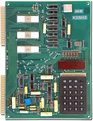
This was my real introduction into the world of assembly language. The machine had six seven-segment displays, a hex keypad, 1K bytes of memory and an 8-bit processor running at 1 MHz. It also had a monitor program stored in 2K of ROM so you could work with the system. It could record your memory contents on an audio cassette, and then reload those bits later. It was amazing what you could do in only 1K of programmable memory.
Using a simple graphics system I have had students use for many years, I was able to put together a set of parts suitable for connecting to our simulated AVR system. All we will need to do is add a bit of logic so our simulator can send signals to these gadgets. Here is a screen shot of the gadget set I put together:
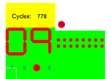
In this image you see the following parts:
Simple LED lights
7-segment LED displays
Text output control
8x1 LED grid, assembled into an 8x8 display
Button that responds to mouse clicks.
The code provided is not set up properly for our work. IT needs to be wrapped up in proper component style classes, but the code does work, and provieds a start on a usable setup for the rest of our simulator labs.
Testing graphical gadgets is not easy. I “hacked” this display together in a few evenings using old-fashioned techniques. While we can test the basic functioning of something, testing what it looks like is another thing entirely. It is possible, just way beyond what we can do in this course.
Running the Demo
Assuming you have cloned the CPUfactory3 repository, all you need to do to try it out (after installing the needed library) is do this:
$ cd cosc2325/CPUfactory3
$ make
$ ./CPUfactory3 -g
The make file has a run task that will run the application, but not in
graphics mode.
Press the “q” key to halt this graphics display.
Click the mouse anywhere in the screen to get the current mouse coordinates. The HEX display will switch from counting up to counting down if you click the mouse anywhere on the screen as well. Clocking on the small “On” button will toggle it from red to green.
All of the code provided is fresh from a serious “blasting” session. I managed
to gt several things running, and am leaving that code in a fairly ugly state.
Your team should clean up some of this code to make it come up to our
standards. All provided code does pass the cpplint test at [resent.
Warning
Running make test will fail, because some of the files needed are to be
provided by you. I have left test code here to exercise parts we havenot
built yet. You are free to use these for your own testing.
The modular-make setup here has been tested on all three major platforms,
and works as expected. The actual development version of this project is being
tested on Travis-CI, something we will set up in a later lecture.
