Help! My lights are making noise!
Read time: 46 minutes (11670 words)
So far, we have written simple programs that do basically one thing at a time.
What if we want to do multiple things? What we need to do is multi-task.
Now some folks are good at this, others not so good. Fortunately, we are not
going to try to help people multi-task, we are going to help our
microcontroller handle more than one thing at the same (well almost) time.
So, what should we do? Well, to keep things simple, let’s combine our blinky light code and our buzzer code and see if we can do both in one program! I want the buzzer to sound each time the LED lights. Just to make things a bit more interesting, let’s also consider that we have one more thing to do, and we want that thing to happen about 50 times per second. Phew! How do we handle all this?
Timing analysis
Before we get into how we will make more than one thing happen at the same time, we need to do a few simple calculations. First, remember that our processor is running at 16MHz, which means that we can run on the order of 16,000,000 instructions each second - sounds like a bunch. How many instructions will each job we have defined take to complete? My bet is - not that many!
Buzzer timing
As we saw in our work on the buzzer, we need to cause the buzzer to pulse at a rate of 4000 times per second to get a reasonable noise out of our little piezo buzzer. In thinking about this, it seems we need to flip the pin on and off at that rate to cause one full cycle of the buzzer to occur. Than means we need to toggle (compliment) the outputs at twice that rate - or 8000 times per second. Given the speed of our little chip, that means we can run about 2000 instructions before we need to toggle the buzzer pins. That sounds like more than enough!
Blinky LED timing
This one was easy, we want the light to blink on every second or so. Once again, if we want the light to come on at one second intervals, we toggle it twice each second! Blinking the LED is basically the same as toggling the buzzer pins, only here, we toggle a single pin.
Special Task
The last, unnamed task needs to happen 50 times per second. What it will do, we will figure out later. For now, we will simply call a procedure to do something 50 times per second. To check that we have timed this right, we will toggle a pin on the Arduino and check it with an oscilloscope.
Summary of basic timing
With all of these simple calculations in mind, it looks like we need to set up a program to call a buzzer toggle routine 8000 times per second. If we can get interrupts happening at this rate, we have a good start on our program.
We need to let 8000/50 = 160 interrupts go by before we call the special task code. Finally, we need to let 4000 interrupts go by before we call the LED blink toggle code.
Sounds like an interesting chunk of code to develop!
Wiring the Arduino
This experiment will involve three separate signals. We will see one, hear another, and for the third we will need an oscilloscope!
Defining the pins
The first thing we need to do is to define how the Arduino will be wired.
Let’s collect the pin assignments into a simple include file so our code is
more generic, and it is easy to rearrange pin assignments if needed. This is my
config.h file:
1 2 3 4 5 6 7 8 9 10 11 12 13 14 15 16 17 18 19 | ; config.h - pin assignments for this project
#include <avr/io.h>
#define LED_PORT _(PORTB)
#define LED_DIR _(DDRB)
#define LED_PIN 5
#define BUZZ_PORT _(PORTB)
#define BUZZ_DIR _(DDRB)
#define BUZZ_PIN 4
#define PULSE_DIR _(DDRD)
#define PULSE_PORT _(PORTD)
#define PULSE_PIN 7
// include this line to avoid SFR_REG issues
#define _(s) _SFR_IO_ADDR(s)
|
You can see that the include for the processor is in this file meaning all we need to do is to include this file in all of our assembly language files. Everything we need will be defined through that one include!
Wiring this project is simple. Just add the buzzer you used for the previous project, and we will use the onboard LED. The third task must be checked with an oscilloscope I will bring to class.
Organizing our code
To make it easy to keep track of all the parts of this project, we will try to isolate functions in files associated with those functions.
main.S- the main program for the project (configures the chip)timer.S- set up timer and define timer interrupt handlerbuzz_task.S- buzzer taskled_task.S- LED taskpulse_task.S- special purpose taskconfig.inc- definitions related to the project
Since we have greatly simplified our Makefile, all you need to do is get a
folder set up with the provided Makefile and these six files.
On to the code
Now that we have the basic idea of what we want to do, let’s see if we can get
something working. We start off by noting that we need some kind of signal that
will tell us to do something every 1/8000 of a second. Last time, we saw how to
set up Timer0 to generate just such a signal. But we have more than one
thing to do, so how does this help.
A Multi-tasking kernel
What we will do is set up the timer to go off 8000 times a second. We will use an interrupt handler just like we did in our last lab, but this time all we will ask the handler to do is to set a trigger variable to one and quit! Huh?
Remember what our main routine was doing while we used the interrupt to blink our light? Basically, it was doing nothing. This time, we will set up our main code to do all of our real work, but we will use the trigger variable to decide what we are to do and when! Here is how it works (in “C”):
int trigger = 0;        // will be set to 1 by ISR
...
while(1) {
    if(trigger == 1) {
        // interrupt went off
        // do work
        trigger = 0;
    }
}
Now the main loop is looking to see if the trigger signal went off. This will happen when the interrupt handler is run. We will do some work, then clear the trigger variable. The main loop will then do nothing until the next interrupt. (It seems we are back to polling here, but we will make it more interesting in a bit.)
In order for this to work, whatever we intend to do when the trigger is sensed must happen fast enough that we get done before the next interrupt goes off. For our experiment, this will be no problem.
Let’s expand this logic a bit and take care of the buzzer first. According to our calculations, we need to trigger the buzzer every time the trigger is sensed. Easy, just call a simple routine that includes the code we showed above to swap the signals on the two pins:
while(1) {
    if(Trigger == 1) {
        BuzzerTask();
        Trigger = 0;
    }
}
...
void BuzzerTask() {
    // swap signals on defined pins
}
Now, we actually have a number of tasks to take care of, so we can extend this code easily to deal with those:
while(1) {
    if(trigger == 1){
        BuzzerTask();
        LEDTask();
        AuxTask()
    }
    trigger = 0;
}
But wait! We said that the other tasks do not need to happen every time the trigger is set, but only every so often. How do we handle that? Well, if we set up a counter for each defined task, we can let the task code figure that out:
int LEDcounter = 0;

void LEDTask() {
    LEDcounter++
    if(LEDcounter == 100) {
        // do work
        LEDcounter = 0;
    }
}
This would make the LED task only do real work when its counter reached 100 - or every 100th interrupt. See how it works? Using a scheme such as this will let you handle a bunch of simple tasks easily.
Let’s build the code and try it out!
Building the Kernel code
In our previous lecture on interrupts, we used Timer0 to generate our
interrupts. Timer 0 is an 8 bit timer that can only count to 255 before
rolling over. We need to be able to count higher than that for this
experiment, so we will need a bit of trickery to get things working!
Timer routines
Basically, we will configure Timer0 as before, but we will set it up to run
at 1/8 the processor clock speed. By using the overflow scheme, that means we
will be generating interrupts at a rate of 16000000 / 8 / 256 = 7812 times per
second, close enough to our target rate of 8000.
Here is the code we need to make the timer work this way (details are described in the processor data sheet):
1 2 3 4 5 6 7 8 9 10 11 12 13 14 15 16 17 18 19 20 21 22 23 24 25 26 27 28 29 30 31 32 33 34 35 36 37 | ; timer.S - Timer1 code for interrupt blink-buzz
#include "config.h"
.global Timer0Setup
.global TIMER0_OVF_vect
.global trigger
.equ MAX_COUNT, 1 ; counts per trigger
.section .data
trigger:
.byte 0 ; set to 1 to fire off tasks
ISRcount:
.byte 0 ; interrupts before trigger
.section .text
;----------------------------------------------------------------------
; Initialize Timer 0 for interrupts
;
Timer0Setup:
in r16, _(TCCR0B)
andi r16, 0xf8 ; clear control bits
ori r16, (1 << CS01) ; divide by 8 = 7812Hz
out _(TCCR0B), r16 ; set timer clock
sbi _(TIFR0), (1<< TOV0); clear interrupt flag
;
lds r16, TIMSK0 ; get interrupt mask reg
ori r16, (1 << TOIE0) ; enable interrupts
sts TIMSK0, r16
out _(TCNT0), r1 ; zero the timer counter
sts ISRcount, r1 ; zero the Interrupt counter
;
sei ; let the fun begin
ret
|
Note
This code is set up to use a counter to skip some number of interrups before setting a trigger variable to be used to launch the task code. We are not using that here, but it is useful for other experiments.
The Timer ISR routines
With the timer properly initialized, the ISR is pretty simple:
1 2 3 4 5 6 7 8 9 10 11 12 13 14 15 16 17 18 19 20 21 22 23 24 25 26 27 | ;----------------------------------------------------------------------
; Timer0 overflow ISR
;
TIMER0_OVF_vect:
; save callers registers
push r0
in r0, _(SREG) ; get flags
push r0
push r24
;
lds r24, ISRcount ; get the counter
inc r24
sts ISRcount, r24
cpi r24, MAX_COUNT ; big enough?
brne 1f
ldi r24, 1 ; trigger tasks
sts trigger, r24 ; reset the ISR counter
sts ISRcount, r1
;
1:
pop r24
pop r0
out _(SREG), r0 ; recover flags
pop r0
reti
|
All we need to do is set the trigger and we are done. This is almost too easy!
Place this code in a timer.S together with the other timer setup code.
The main routine
Here is the initialization we need in our main code:
; main.S - avr-gcc assembly language

#include "config.h"

        .extern Timer0Setup
        .extern trigger

        .extern buzz_task
        .extern buzz_init
        .extern led_task
        .extern led_init
        ; .extern pulse_task
        ; .extern pulse_init

        .section    .text
        .global main

main:
        ; set up the system clock
        ldi     r24, 0x80               ; set up prescaler
        sts     CLKPR, r24
        sts     CLKPR, r1               ; set to full speed
At this point in our main code, the interrupt table is set up properly, but we need to initialize the chip, timer and all the tasks. We will set up initialization routines in each task file and simply call those routines here:
1 2 3 4 5 | ; initialize the system
call Timer0Setup
call buzz_init
call led_init
; call pulse_init
|
Note
Since I have no need for the pulse task at the moment, I commented out that code.
We have one more chunk of code to set up. Our main code needs to check the trigger variable and call the tasks into life. Place this code right after the call to the timer setup routine:
1 2 3 4 5 6 7 8 9 10 | ; task management loop
1:
lds r16, trigger
cpi r16, 1 ; gone off yet?
brne 1b ; wait for it
call buzz_task
call led_task
; call pulse_task
sts trigger, r1 ; turn off the trigger
rjmp 1b
|
The task framework
Now that we have an interrupt going off every so often, we can turn to the code needed to make our tasks work as we wish. Here is the framework for a single task. Modifying this code for each designated task is pretty easy:
1 2 3 4 5 6 7 8 9 10 11 12 13 14 15 16 17 18 19 20 21 22 23 24 25 26 27 28 29 30 31 32 33 34 35 36 37 38 39 40 41 42 43 44 45 | ; buzz_task.S - avr-gcc assembly code
#include "config.h"
; buzzer task
;
; hook the buzzer to PB4 for this task
.global buzz_task
.global buzz_init
.equ BUZZ_MAX, 1 ; service every interrupt
.section .data
buzz_counter:
.byte 0
.section .text
;buzz_task - piezo buzzer at 4000Hz
; uses r16, r17
;
buzz_init:
sbi BUZZ_DIR, BUZZ_PIN ; set to output
cbi BUZZ_PORT, BUZZ_PIN ; start this one with 0
ret
buzz_task:
lds r16, buzz_counter
inc r16
sts buzz_counter, r16
;
ldi r17, BUZZ_MAX
cpse r16, r17
rjmp 1f
;
in r16, BUZZ_PORT
ldi r17, (1 << BUZZ_PIN)
eor r16, r17
out BUZZ_PORT, r16
;
2:
sts buzz_counter, r1 ; zero the counter
1:
ret
|
We do the work needed for this task above the line labeled 2 above
Testing our interrupts
As a test of the basic logic we have presented here, I set up pulse_task to
fire the logic to toggle the pulse pin each time it is called (max task
count value is 1). I hooked an oscilloscope to the pulse pin to see
how often they are being triggered. Here is what I saw:
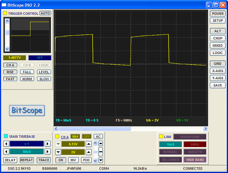
This figure shows an interrupt being triggered about every 125 microseconds, which works out to 8000 times per second, right on the money! Now, we can go off and set up the remaining tasks
Blinking the LED
Now that we have the basic interrupt system running, let’s slow things down and blink the light.
In this task, we need to let about 4000 interrupts go by. That is too many to
count with a simple 8 bit register, so we need a 16 bit counter to do the job.
This code is a bit more involved, since we need to do 16-bit math. The AVR has
a few registers it treats as 16 bit registers, used mainly for indirect
addressing. Since we do not need any of that at the moment, we will use one
register pair (r26, r27) as a 16 bit register. The AVR calls this pair X:
Here is our LED task:
1 2 3 4 5 6 7 8 9 10 11 12 13 14 15 16 17 18 19 20 21 22 23 24 25 26 27 28 29 30 31 32 33 34 35 36 37 38 39 40 41 42 43 44 45 46 47 48 49 50 | ; led_task.S - avr-gcc assembly code
#include "config.h"
; LED task
;
; This task uses the built-in LED on the Teensy
.global led_init
.global led_task
.global led_on
.equ LED_MAX, 4000 ; trigger every 1/2 second
.section .data
led_countH: .byte 0
led_countL: .byte 0
.section .text
led_init:
sts led_countH, r1 ; clear counter
sts led_countL, r1
; set up LED port
sbi LED_DIR, LED_PIN ; set up the output port (bit 6)
cbi LED_PORT, LED_PIN ; start off with the LED off
ret
led_task:
lds r26, led_countL ; load counter
lds r27, led_countH
adiw r26, 1 ; increment counter
sts led_countL, r26 ; save it back
sts led_countH, r27
;
cpi r26, LED_MAX & 0xff ; Compare low byte
ldi r16, LED_MAX >> 8
cpc r27, r16 ; Compare high byte
brne 1f ; branch if not equal
;
in r16, LED_PORT ; toggle LED pin
ldi r17, (1<<LED_PIN)
eor r16, r17 ; flip the LED bit
;
out LED_PORT, r16 ; set the LED pin
sts led_countL, r1 ; and clear the counter
sts led_countH, r1
1:
ret
|
Notice the code we need to check this 16 bit counter against the max defined value.
Buzzing the buzzer
The code needed to make the buzzer work is placed in buzz_task above the line labeled 2:
1 2 3 4 5 | in r16, BUZZ_PORT
ldi r17, (1 << BUZZ_PIN)
eor r16, r17
out BUZZ_PORT, r16
;
|
If you test the code at this point, the buzzer should sound and the LED should blink at about the right rate. Cool, but we wanted to cause the buzzer to sound when the light is on. So, we have a bit more work to do.
Basically, we need to let one task talk to another task. We need to have the LED task set a variable when the LED goes on, and tell the buzzer task to shut things down when the LED is off. Hmmm - let’s see if we can get this working!
First, we need to set up the variable. We will define it in led_task and let
buzz_task see it.
1 2 3 4 | .global led_on
.section .data
led_on: .byte 0
|
And in buzz_task:
1 | .extern led_on
|
Now, we need to set this variable when the LED is on. Unfortunately, since we are just toggling the bit, we do not know if the LED is on or off, so we will just test the right bit. If it is a 1, the LED is on!
1 2 3 4 5 6 7 8 9 10 11 12 13 14 15 | in r16, LED_PORT ; toggle LED pin
ldi r17, (1<<LED_PIN)
eor r16, r17 ; flip the LED bit
;
sts led_on, r1 ; say it is off
sbrs r16, LED_PIN ; skip if it is on
rjmp 2f
ldi r17, 1 ; get a 1
sts led_on, r17 ; say it is on
2:
out LED_PORT, r16 ; set the LED pin
sts led_countL, r1 ; and clear the counter
sts led_countH, r1
1:
ret
|
With this change, we have the led_on variable set if the LED is on. Now, we
can use this variable to decide if we should toggle the buzzer pins. (Skipping
this will cause the buzzer to shut off.)
1 2 3 4 5 6 7 8 9 10 11 12 13 | cpse r16, r17
rjmp 1f
;
lds r16, led_on ; see if the LED is on
cpi r16, 1 ;is it on
brne 1f
cpi r16, 1 ; test it
brne 2f ; not on - no buzz
;
2:
sts buzz_counter, r1 ; zero the counter
1:
ret
|
Try this change! With any luck, the buzzer will only sound when the LED is on!. Cool, multi-tasking working in a neat way!
What about that last task?
We had one last task to handle. This one is an example of a task that could be expanded to fire off a signal to a servo. If you look into the documentation for servos, you discover that they like to have a pulse sent their way about 50 times a second. (Actually, that number is soft, they work well with a range of values.)
Let’s set up a simple task and see if we can have is generate a short pulse we can look at on the oscilloscope. This will not be enough code to run the servo, but it should give you ideas.
Here is the task we will use:
1 2 3 4 5 6 7 8 9 10 11 12 13 14 15 16 17 18 19 20 21 22 23 24 25 26 27 28 29 30 31 32 33 34 35 36 37 38 39 40 41 42 43 44 | #include "config.h"
; pulse_task - Servo task - service at 50Hz
.global pulse_task
.global pulse_init
.equ PULSE_MAX, 160
.section .data
pulse_countH:
.byte 0
pulse_countL:
.byte 0
.section .text
pulse_init:
sts pulse_countH, r1 ; clear counter
sts pulse_countL, r1
sbi PULSE_DIR, PULSE_PIN
ret
pulse_task:
lds r26, pulse_countL ; load counter into X
lds r27, pulse_countH
adiw r26, 1 ; increment counter
sts pulse_countL, r26 ; save it back
sts pulse_countH, r27
;
cpi r26, PULSE_MAX & 0xff ; Compare low byte
ldi r16, PULSE_MAX >> 8
cpc r27, r16 ; Compare high byte
brne 1f ; branch if not equal
;
in r16, PULSE_PORT ; toggle LED pin
ldi r17, (1<<PULSE_PIN)
eor r16, r17 ; flip the LED bit
;
out PULSE_PORT, r16 ; set the LED pin
sts pulse_countL, r1 ; and clear the counter
sts pulse_countH, r1
1:
ret
|
You should be able to add this task to your code. When I ran the resulting
program, this is what I saw on the output pin we set up for Task3:
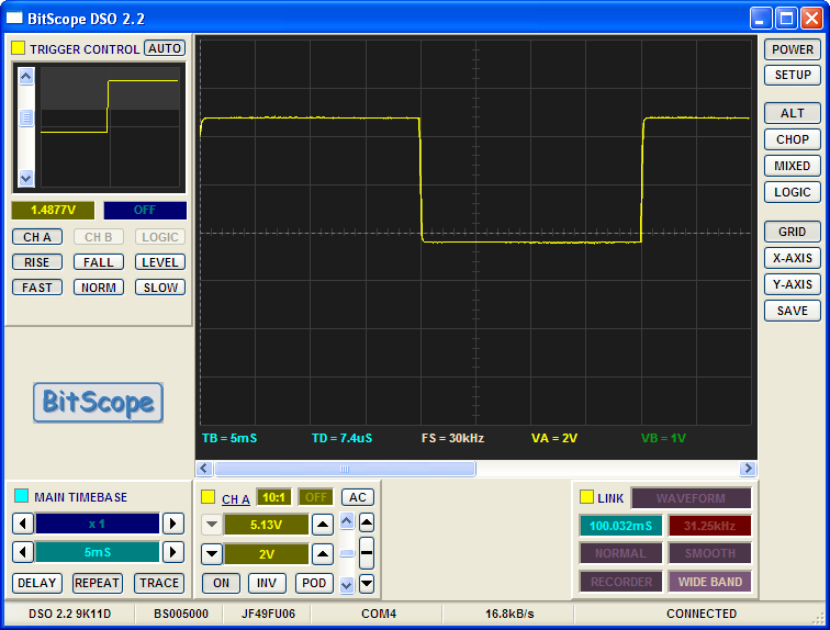
That is one call every 20ms, which works out to our target of 50Hz. Looks like we have a program we can work with!
Testing your code
As your code gets more complex, you will soon wish you had better tools to help debug your code. Fortunately, there are many such tools available, some free, some not free. Here are some references to tools we might use:
Further Reading
In case you are interested in seeing a more sophisticated way to set up a multi-tasking kernel on the Arduino, here is a paper to get you started:
