AVR Timers
Read time: 31 minutes (7964 words)
We will begin our look at the internal components that surround the central processor in an AVR chip by examining the timers provided in each chip. The source for all the information you need to study in order to use one of these, or any internal component, is the datasheet for the chip.
The atmega328p, has a set of timer modules that can be used to signal the
processor when some amount of time has elapsed. These modules can be used as
simple alarm clocks, or can be used to generate pulse width modulation
signals commonly used to control the speed of motors, or the brightness of
lights.
The available timer modules in the atmega328p include these:
Timer0 - an 8-bit counter with PWM capability
Timer1 - a 16-bit counter with PWM capability
Timer2 - an 8-bit counter with PWM capability
Watchdog Timer - used to reset the processor if programs run amuck!
Counter Operation
The timers operate in two basic modes:
Normal mode - the counter simply counts up and “rolls over” to zero
Clear Timer on Compare Match(CTC) mode - clears the counter when it matches some value
Selection of these modes is controlled by specific bits in a control register.
WGM (Waveform Generation) bits
COM (Compare Output Mode) bits
Normal Mode
In this mode, the timer starts running when we load a specific value into a count register. This register will be incremented automatically by the system clock, possibly altered by a “scaling” function we can also configure. By combining control of the master system clock, and specific timer “prescalers” we can decide how long it will take for the timer counter to reach a point where a signal will be generated.
For instance, loading a zero into the counter means it will take as many ticks as the counter can hold before the timer signal will be generated. This can be 256 ticks for an 8-bit counter, or 65536 ticks for a 16-bit timer counter.
In normal mode, when the timer “rolls over”, a flag bit will be set. That flag can either be detected by your program using periodic “polling”, where your program peeks at the flag to see if it has gone up, or the flag can generate an interrupt and we can handle the timer event in an interrupt handler.
In either case, code must reset the flag signal so another timer event can be detected. This allow the timer to run continuously, and we can generate all kinds of signals to external devices using this scheme, with little load placed on our code!
Compare Match Mode
In this mode, the counter is incremented as before, but the timer signal is generated when the value in the counter matches a value programmed into a second register.
Controlling the setting ot the compare register is the foundation to Pulse
Width Modulation (PWM). An output pin will be either 0 or one depending on if
the value in the timer counter is above or below the compare value.
Timer Signals
When the counter reached the max value it can hold, and “rolls over” to zero, a
signal will be generated in a flag like TOV0 for Timer0. This flag can be
configured to generate an interrupt, or simply checked by software (polling).
Activating the Timer
We start the timer by configuring a source for the clock signal used to
increment the counter. Timer0, for instance, can be controlled by an internal
counter derived from the master clock, or from an external source of pulses on
the pin labeled T0.
The choice is set in register TCCR0B.
TCCR0A Register
Bit0-1 -
WGM00-1- Waveform Generation ControlBits4-5 -
COM0B0-1Compare match output B (OC0B)Bits6-7 -
COM0A0-1COmpare match output A (OC0A)
TCCR0B Register
Bit0-2 -
CS00-02Clock select bitsBit3 -
WGM02Waveform control bitBits6-7 -
FOC0A-BForce Output compare
TCNT0 Register
This is the primary counting register.
OCR0A Register
This register is set with the 8-bit value to be compared.
OCR0B Register
This is a second compare register
TIMSK0 Register
This register contains bits used to control interrupts.
Bit0:
TOIE1interrupt enable for Timer 0 overflowBit1:
OCIE0Ainterrupt enable on compare match ABit2:
OCIE0Binterrupt enable on compare match B
TIFR0 Register
This register contains flags indicating interrupts have happened:
Bit0:
TOV0- counter overflow has occurredBit1:
OCF0A- match on compare ABit2:
OCF0B- match on compare B
Configuring the Timer
A typical setup for Timer0 could involve programming these bits:
TCCR0A = 0 (Normal mode operation)
TCCR0A = (1 << COMA0A1) | (1 << COM0A0) Set OC0A on compare match
TCCR0A = (1 << COM0B0) Toggle OC0B on compare match
Watchdog Timer
In some applications, you might like to be able to reset the processor if the program runs off and does something unexpected (Windows, anyone?) A watchdog timer can do this.
Basically, this timer will generate a reset signal if it is allowed to go off. Since the reset signal restarts the loaded program, if we allow this timer to reach the signal point, the program will simply restart. In normal program operation, we will not allow this to happen. The program will need to reset the watchdog timer system to avoid allowing the reset signal.
The watchdog timer can also be configured to generate an interrupt, which can be used to deal with external devices that are supposed to complete an action in some specified amount of time. This interrupt can also be used to allow the processor to do some final action before resetting the system.
Pulse-Width-Modulation
One of the most common techniques for controlling the brightness of a light,
the tone of a buzzer, or the position of a servo is called
pulse-width-modulation or PWM. This scheme is easy for a
microcontroller to use and does a simple job for us - it lets the digital
on-off machine generate a signal that acts like a varying voltage in the effect
it has on these electrical components.
How does it work
Basically PWM is simple to understand. Let’s look at controlling the brightness of an LED as an example.
Instead of turning the LED full on or full off, we will pulse it on and off at some frequency. We choose this frequency so it is fast enough so our eyes cannot see the LED turn on or off. Obviously, if we pulse the light on and off evenly at a high frequency, it is off half the time and on half the time. To our eyes, it will look like it is half the brightness it would have if it was on all the time.
Hmmm, what would happen if we varied the amount of time it is on and off from 50% on - 50% off to some other value, like 25% on-75% off. The LED would be dimmer yet. If we reversed this, the LED would be a bit brighter.
So, the basic idea of PWM is to provide a simple way to vary the amount of on time and off time smoothly from full off to full on during some fixed amount of time. We could certainly do this manually, but it is a common enough problem that most microcontrollers provide an internal device that can do this job for us.
AVR PWM Support
In our AVR chip, the timers we have been using can be set up to drive a PWM system. Basically, they work by setting up a counter that counts upward to some maximum value, then the counter resets and starts counting over. We used this scheme to generate our interrupt for the tasking kernel we looked at last time.
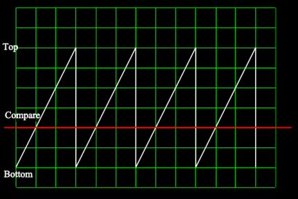
Here is a plot of the counter value as it increases over time:

In this diagram, the timer counter is varying between a bottom setting and
a top setting.
What we need to add to this mechanism is another device known as a
comparator. This device is basically a register that holds some data value
and logic that can compare the current value of the timer counter and the
comparator register. The unit outputs a zero on a designated output pin if the
current count is below the set value and logical one on the same pin if it is
above the set value. We use this output to control our LED. Setting the
comparator value to zero will keep the LED on at full brightness, and setting
it to the value where the timer counter resets will keep the LED off. Any
value in between will result in a variable brightness!
Here is the sawtooth pattern with the value of the comparator register shown:
The output of the comparator will be this:
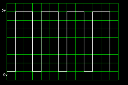
If we use this signal to control our LED, it will give us the variable brightness we are after!
We will explore this setup in more detail later, as part of our introduction to interrupts.
