Programming the AVR Timers
Read time: 25 minutes (6354 words)
Let’s explore some “C” code and see if we can create a simple signal that can drive a Piezo buzzer.
The Piezo Buzzer
Here is the buzzer we will use
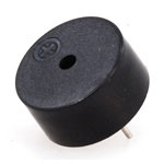
- a crystal inside of this flexes when a voltage is applied across the leads
when it flexes, it pushes air out of the way.
Flex it fast enough and those air pulses hit your ear making noise
You control the tone by the pulse rate
Buzzer Code
Here is the start of our code
// Example Arduino code to sound a Piezo buzzer

#include <avr/io.h>
#include <util/delay.h>

#define CLOCK_PRESCALE(n)   (CLKPR = 0x80, CLKPR = (n))
#define BUZZER_CONFIG       (DDRB |= (1<<4))
#define BUZZ_ON             (PORTB |= (1<<4))
#define BUZZ_OFF            (PORTB &= ~(1<<4))
This code sets up the chip clock so it runs at a slower than full speed. There are defines that set up the output pin and toggle that pin on and off. We will use these macros in the main code.
Chip setup
Next we configure the chip
int main(void){
    CLOCK_PRESCALE(0);
    BUZZER_CONFIG;
We are going to connect the buzzer between Arduino pin 12 (PORTB bit 4) and the one of the ground lines on the opposite side of the board.
The buzzer loop
Finally, we enter the main loop
    while(1) {
        BUZZ_ON;
        _delay_us(200);
        BUZZ_OFF;
        _delay_us(200);
    }
Connecting the buzzer
Here is how to hook up a simple Piezo buzzer to output pin 12 on the Arduino
board (PB4 on the chip itself).
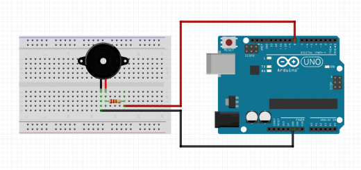
Note
This image shows the buzzer connected to another pin on the Arduino. Any output pin will do, you just need to modify the configuration definitions to make it work.
Here is a picture of the chip, with all of the pins identified. This will help in hooking up other stuff to the board:

What is wrong with this?
Running this code makes noise (it did on my system, but not very loud!)
The program works, but it consumes all the processor’s attention
That wastes power we could use for other purposes. One way to solve this is to
us an internal Timer.
Warning
There is one more problem with this code: IT WILL NOT SHUT UP! The code runs forever, generating an annoying tone. At least we know it works!
A Timer is just a simple counter that cab be set up and let run. The timer counts using the system clock. Once the timer reaches a max value, it rolls over and we can detect that!
AVR Timers
The chip on the Arduino has four internal timers that go by these names:
Timer0- 8 bit counter
Timer1- 16 bit counter
Timer3- 16 bit counter
Timer4- 10 bit counter
Hmmm, wonder what happened to Timer2?
Clock source
We mentioned that the timer counts using the system clock. To give more control
of the timing we can divide that system clock using something called a
prescaler to extend the time it takes reach the max count value.
The possible prescaler settings available on these timers are:
Clock / 8
Clock / 64
Clock / 256
Clock / 1024
Timer counting rates
On the Arduino, we can configure timers to increment the counter every:
8/16000000 = 0.5us
64/16000000 = 4us
256/16000000 = 16us
1024/16000000 = 64us
Setting the timer count
Each timer has a fixed number of bits available for its counting register. That means they can count up to:
255 for an 8-bit timer
1024 for a 10-bit timer
65536 for a 16-bit timer
We can detect when the timer “rolls over” from the max value it can hold to zero. That event can signal an interrupt, or simply set a flag we can check in our code. That is called “polling”.
The timers begin operation when we load a count into their counting register. If we start the timer with zero, it will rake time to reach the maximum count. If we choose to load some value other than zero in the counter, the time it takes to “roll over” will be shorter.
Maximum timer times
We will be using the 8-bit Timer0 timer for this experiment. With the available prescallar values, we cna get these times out of the timer:
256 * 0.5us = 128us = 7812Hz
256 * 4us = 1.024ms = 976Hz
256 * 16us = 4.096ms = 244Hz
256 * 64 = 16.384ms = 61Hz
Of course, we can adjust these numbers. We also have control over how fast the main clock ticks, usina another scaling register that divides down the main system oscillator.
Detecting the roll over
We can deal with the signal one of two ways:
write code that checks for roll over every so often (polling)
configure the chip to generate an
interruptwhen it happens
For this experiment, we will use “polling”.
Configuring the Timer
In order to use a timer, we must set it up and start it running. There are two tasks we need to do:
set the prescaler value
preload the counter
For Timer0, the control registers we use to control the count rate is:
Timer/Counter Control Register B -
TCCR0B
Bit 0 =
CS0Bit 1 =
CS1BIT 2 =
CS2
Setting the prescaler
CS2 |
CS1 |
CS0 |
Function |
0 |
0 |
0 |
Timer stopped |
0 |
0 |
1 |
clock/1 |
0 |
1 |
0 |
clock/8 |
0 |
1 |
1 |
clock/64 |
1 |
0 |
0 |
clock/256 |
1 |
0 |
1 |
clock/1024 |
Setting the preload count
THe register Timer0 uses for counting is:
Timer/Counter0 count register -
TCNT0This register is set with an initial counter value.
Setting the count starts the timer (if enabled)
Detecting the roll over
Each timer has a bit that is set whenever the timer overflows. For Timer0
thise bit we will use is this:
- Timer Interrupt Flag Register -
TIFR0
The bit we will examine is
TOV0(overflow).
Polling code
We will write the polling code in assembly language. THis file looks like others we have set up, except that we need to make the single function in this file global`. THe “C” code will reference this function to do the delay. In this example, we are not passing any data between “C” and assembly language code. Doing that is a topic for later.
Here is the timer code. This function configures the timer, starts it up for the delay time, then shuts it down when done.
1 2 3 4 5 6 7 8 9 10 11 12 13 14 15 16 17 18 19 | #include "config.h"
.section .text
.global timer_delay
timer_delay:
out _(TCNT0), r1 ; zero counter
ldi r24, 0x3c ; set compare value
out _(OCR0A), r24
ldi r24, (1 << WGM01) ; CTC max trigger
out _(TCCR0A), r24
ldi r24, (1 << CS02) | (1 << CS00) ; clk/1024
out _(TCCR0B), r24
1: sbis _(TIFR0), 1 ; (1 << TOV0) ; check interrupt flag
rjmp 1b
out _(TCCR0B), r1
ldi r24, (1 << OCF0A)
out _(TIFR0), r24
ret
|
Skipping instructions
Some AVR instructions are a bit funny. In this code you will see the sbis
instruction:
- Test some condition (bit in register is set)
If the condition is met, skip the next instruction
- Otherwise, they execute the next instruction
Usually this is a jump of some kind
The result is like our conditional branch, but it takes two instructions
Is this better?
With this code, the processor is not really stuck in a loop until the overflow bit gets set, even though that is how we set this delay function to work. We could be off doing other things until that flag bit gets set. This is sure easier to control that that ugly nested counting loop we used earlier!
Rewriting the Code
We will set up this project in a new folder with a single Makefile. The
Makefile shown here can build any project involving C or AVR
Assembly code:
1 2 3 4 5 6 7 8 9 10 11 12 13 14 15 16 17 18 19 20 21 22 23 24 25 26 27 28 29 30 31 32 33 34 35 36 37 38 39 40 41 42 43 44 45 46 47 48 49 50 51 52 53 54 55 56 57 58 59 60 61 | # source files
TARGET := $(shell basename $(PWD))
CSRCS := $(wildcard *.c)
COBJS := $(CSRCS:.c=.o)
SSRCS := $(wildcard *.S)
SOBJS := $(SSRCS:.S=.o)
OBJS := $(COBJS) $(SOBJS)
LST := $(TARGET).lst
# define the processor here
MCU := atmega328p
FREQ := 16000000L
# define the USB port on your system
#PORT := /dev/ttyACM0
PORT := /dev/tty.usbmodem14101
PGMR := arduino
# tools
GCC := avr-gcc
OBJDUMP := avr-objdump
OBJCOPY := avr-objcopy
DUDE := avrdude
UFLAGS := -v -D -p$(MCU) -c$(PGMR)
UFLAGS += -P$(PORT)
UFLAGS += -b115200
CFLAGS := -c -Os -mmcu=$(MCU)
CFLAGS += -DF_CPU=$(FREQ)
LFLAGS += -mmcu=$(MCU)
.PHONY all:
all: $(TARGET).hex $(LST)
# implicit build rules
%.hex: %.elf
$(OBJCOPY) -O ihex -R .eeprom $< $@
%.elf: $(OBJS)
$(GCC) $(LFLAGS) -o $@ $^
%.o: %.c
$(GCC) -c $(CFLAGS) -o $@ $^
%.o: %.S
$(GCC) -c $(CFLAGS) -o $@ $<
%.lst: %.elf
$(OBJDUMP) -C -d $< > $@
# utility targets
.PHONY: load
load:
$(DUDE) $(DUDECONF) $(UFLAGS) -Uflash:w:$(TARGET).hex:i
.PHONY: clean
clean:
$(RM) *.hex *.lst *.o *.elf
|
main.c: Setting up
We start off by writing the configuration file we will use for this project:
1 2 3 4 5 6 7 8 9 | #include <avr/io.h>
#define BUZZ_PIN 4
#define BUZZ_DIR DDRB
#define BUZZ_PORT PORTB
#define _(s) _SFR_IO_ADDR(s)
|
We will set this project up a bit differently. This one will use a standard “C” main function that handles the basic buzz logic. We will use Timer0 in compare match mode to do the delay logic. That routine will be written in assembly language.
1 2 3 4 5 6 7 8 9 10 11 12 13 14 15 16 17 18 19 20 21 22 23 24 25 26 | #include "config.h"
extern void timer_delay();
#define BUZZ_ON (BUZZ_PORT |= (1<<BUZZ_PIN))
#define BUZZ_OFF (BUZZ_PORT &= ~(1<<BUZZ_PIN))
void setup() {
BUZZ_DIR |= (1 << BUZZ_PIN);
PORTB = 0;
}
void loop() {
BUZZ_ON;
timer_delay();
BUZZ_OFF;
timer_delay();
}
int main(void) {
setup();
while(1) {
loop();
}
}
|
How it works
Main sets up the chip and timer system
It then loops toggling buzzer pins and calling the timer delay routine
timer.Sconfigures the timer timerIt uses polling in the delay loop to wait for the timer overflow
Overall logic is identical to the “C” example
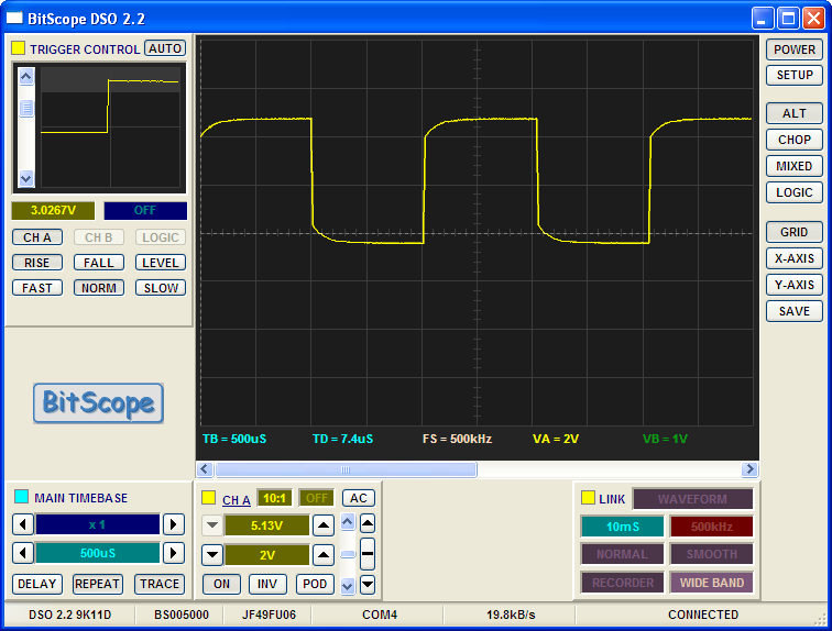
The output signal
Examing the Code
The Makefile used in this project creates a listing file (with en extension
of .lst). This file is a “disassembly” of the final binary code sent to the
processor. Eamining this file is how I discovered the problems with the current
linker. I am still working on figuring out how to control the link step so I can
generate pure assembly language files properly!
